BAS 7015
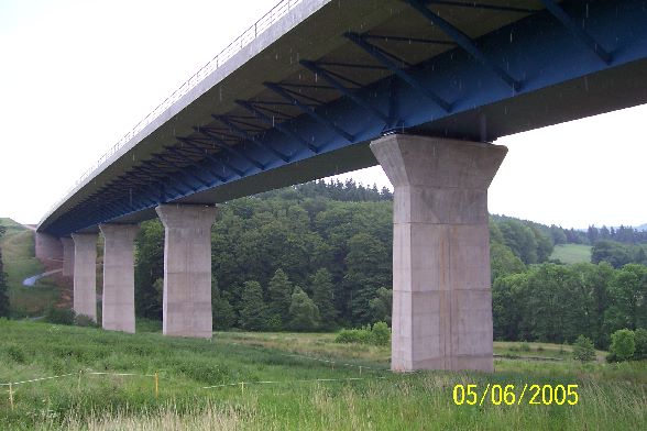
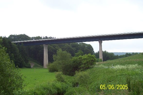
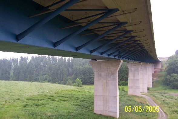
Steinbach Valley bridge
05.06.2005
© Heidi Zengerling
Use of Heidi Zengerling
05.06.2005
© Heidi Zengerling
Use of Heidi Zengerling
05.06.2005
© Heidi Zengerling
Use of Heidi Zengerling
Germany
Thuringia, Germany
Steinbach, Bodenrode
A38 motorway
Girder bridge
Composite steel / concrete
2000-2003
0.00 m
372.00 m
0.00 m
35.00 m
0.00 m
10974.00 m2
in operation
The steel box construction height: 4.65 m<br>Construction costs approximately EUR 28 million<br>Construction period: 28 months<br><br>Information by heidi Zahir:<br><br>During the construction of the BAB A-38 from Göttingen to Hall necessitated a bridge over the Valley of the Steinbach at km 28 + 500 between Heiligenstadt and linen. The BAB crosses the South been observed from the North Valley in an East West direction A 38. The new bridge construction spans the Steinbach, the country road L 2020 between Bodenrode and Steinbach and agricultural roads. The Bauerk has a length of 372 m and a maximum height above Valley of about 40 m. The A38 runs to the East in the cut, in the West on an embankment.<Br><br>The Valley to be bridged is both scenic and ecologically sensitive. The route runs completely in the water protection area in this field. The interventions in nature and the environment should be kept as low as possible. Different variants in prestressed concrete and Steel laminated composites were examined in the course of the planning. Among them was also a variant with a one-piece steel-composite cross-section. The decision was made in favor of the superstructure with one-piece steel composite cross section with only a brace on each axle.<Br><br>The superstructure consists of a one-piece steel composite girder, which bridged 6 fields spans as parallel belt, continuous beam of 54 m + 66 m + 66 + 78 m + 60 m + 48 m. The spans were anagepasst the topography.<Br><br>At the bottom of the Valley is the largest effective span with 78 m. The width of the superstructure between the railings is 29.50 m. This requires lateral stabilizers by diagonal Struts which at the same time visually integrate the Mantel band in the vertical direction under the deck. The diagonal Struts are arranged in circular tubes and are at a distance of 6 m. To get not too shallow diagonal Struts inclinations, the construction height was set at 4.65 m.<Br><br>This height allows at the same time an insert of the steel trough without propping. The building is in the range of a Clothoid a parameter A = 1500 m. The geometry allows however, insert the steel trough on a replacement circuit. The geometric adjustment (max. deviation: 19 cm) to the Clothoid is in the deck. The one-piece steel construction and the top associations were so dimensioned that sequentially replace of the deck on half-width and length of 15 m at any point of the superstructure under a 4 + 0 data preservation of traffic is possible.<Br><br>This is a prerequisite for the execution of one-piece superstructures on motorways.<Br><br>Alternative to slide in the deck was also a stepwise manufacture of the deck in the Pilgrim-step procedure approved. First, the field areas of the deck be concreted and concluded the area above the supports. In this way, the longitudinal strain in the deck over the rest of the weight of the concrete can be minimized. When inserting the deck with subsequent friction, virtually no tensile stresses resulting from the weight of the deck.<Br><br>The composite action is only effective for the extension loads and the loads (Verkehrsverbund)<Br><br>Because the Steinbach Viaduct is required for the Erdmassenlänstransporte, she had to run as an early measure of construction. The construction rights for the bridge was obtained therefore plan approval in September 1999. In addition to the technical aspects, it is particularly geachatet in accordance with plan approval granted on the environmental and landscape protection.<Br><br>The Foundation is in the solid rock horizon formed almost in the entire route from nearly horizontally-lying layers of the Volpriehausen sequence of the lower middle bunter sandstone in the facies of the calibration box threshold. The Middle Bunter of alluvial sand, Solifluktionsschutt, hanging clay, topsoil and other populations is overlaid in the Western flat slope. Thus was founded the building in the Western flat slope in the axis 10-50 as deep foundation on vertical or inclined (8: 1) Großbohrpfählen with a diameter of 1.50 m and lengths of 10-20 m. The stakes include Rock Rock horizon Middle bunter sandstone. The Middle Bunter was cut directly into the Eastern wooded steep slope area in the Achsen60 and 70. These two axes could be established so flat.<Br><br>The storage of the bridge is done on spherical bearings with maximum bearing loads of approx. 24 MN. The longitudinal-detention of the bridge is realized by a Festpfeilergrußße on the longest piers in the axis of 30-50.<Br><br>Due to the very low longitudinal gradient of the gradient (approximately 0.5% in axis 10 and approx. 0.3% in axis 70) and the bridge over two opposite longitudinal lines (DN 300) to the axis must be drained to 40 and able in a tub,. The water of the bridge Board is fed through a pipe into a pillar niche in a Stilling basin and from there in the Regenrückhalatebecken and then by the cleaning basin in the Steinbach. Additionally through the superstructure from the Eastern to the Western abutment a pipe DN 600 of routes dewatering occurs out exit to route water from the water protection area.<Br><br>The building was advertised in late 1999. The supplement was issued end of 1999 on the lowest-priced offer amounting to 28.3 million DM to the construction company J.G. Müller, Wetzlar, commissioned the production of the deck by means of sound car. The steel works were by the company VA TECH VOEST MCE, Linz running.<Br><br>The extensive conditions in the water protection zone II determined the construction process. So, the rainwater holding tanks with all its components and facilities was completed first after the construction site clearance and the manufacture of the Baustraßen. After that was
Ground work on the abutment axis started 10 and pushing off of the screed in the remaining axes.<Br><br>In the period from April to June 2000, the Großbohrpfähle sunk and then produced the foundations, abutments and piers.<Br><br>The manufacturing of steel parts took place in the period from July 2000 to March 2001.<Br><br>The steel parts were transported by truck in shots from about 18-22 m length, height of 4.0 m and widths of 2.50-3.00 m to the construction site and aligned on the pre-Assembly area behind the Western abutment in axis 10, and welded. After welding by 4 shots with a length of approx. 80 m was launching (insert) of the Assembly. For the adjustment rods came up usage. Rocker bearing were used as Verschiebelager with length of 3.00 m and width of 10 cm. A stem beak with a length of 30 m was mounted at the top of the steel trough, which was the reverse thrust line to above, so that the deflection was offset by macimal 85 cm in the projecting State and running aground on the pillar was easily possible to. The Assembly of the Tahltrogs is approx. 2200 tons of construction steel S 355 J2 G3 (ST 52-3). The corrosion protection is carried out according to ZTV-KOR 92. It consists of a base coat, edge protection, and three deck coatings. The last top coat is applied on the construction site.<Br><br>The scarf is frame construction designed as the sichauf supports the Stahllängsträgern and comes from without through tensions through the deck. The deck is made length and the width by 29 m in the Pilgrim steps in B 35 sections of approximately 25 m. To operate the road surface, a crane truck with a weight of approximately 30 tons is mounted on the sound truck. The total weight of the sound car is about 250 tons.
A map is loading